
For automatic actuation of industrial valves
with rotating throttle elements
- Counterclockwise rotation for VETEC series 72, 73, 82 (counterclockwise closing) - Rotary angle 75°.
- Clockwise rotation for VETEC series 62 (clockwise closing) - Rotary angle 90°.
Technical data
| Application | Control and on/off application | |
|---|---|---|
| Sizes |
60 to 10000: Edition 2010 60 to 1200: Edition 2020+ | |
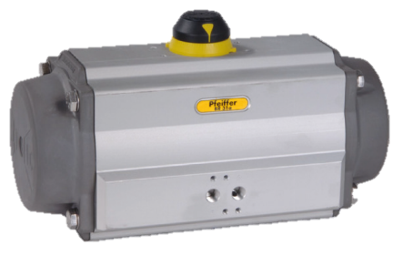
| Design | Type BR31a (SRP) | Double piston; single acting with spring return; encapsulated spring assemblies |
| Type BR31a (DAP) | Double piston; double acting without spring return; without spring assemblies | |
| Other versions | For low temperatures; quick-closing; made of stainless steel | |
| Actuator movement |
Rotary Left-turning for series 72, 73, 82 (counterclockwise closing) Right-turning for series 62 (clockwise closing) | |
| Rotary angle |
0 to 75 ° for series 72, 73, 82 0 to 90 ° for series 62 | |
| Power supply | Pneumatic | |
| Control air range | 3 to 6 bar | |
| Safety function | Type BR31a (SRP) | Spring force closes (FC) or spring force opens (FO) |
| Type BR31a (DAP) | Without | |
| Torques | Type BR31a (SRP) | 13 to 4068 Nm |
| Type BR31a (DAP) | 35 to 10007 Nm | |
| Permissible ambient temperature |
-40 to +80 °C -55 to + 80 °C (version for low temperature) | |
| Differential pressures for actuator sizing | TY005.069 | |
| Swing angle limitation (optional) | Internal or external stroke limitation (end stops) | |
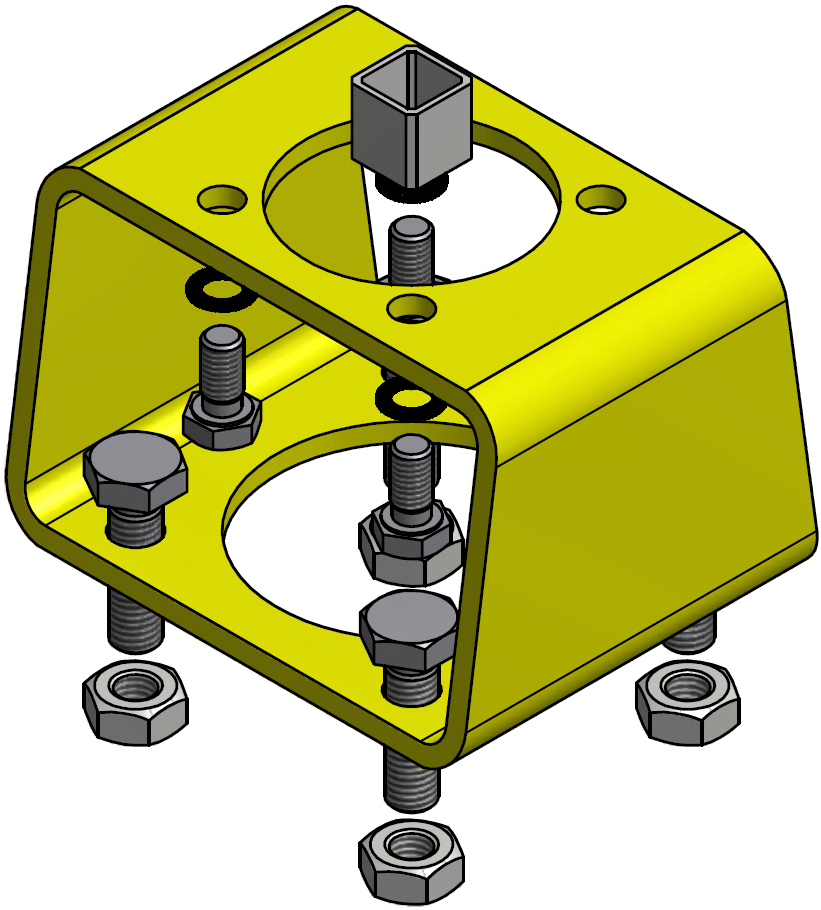
| Interface to valve | according to DIN EN ISO 5211 | |
| Interface for attachments | In accordance with VDI/VDE 3845-1 (EN 15714-3) and VDI/VDE 3847 (IPM attachment block) | |
| Conformity | EAC |


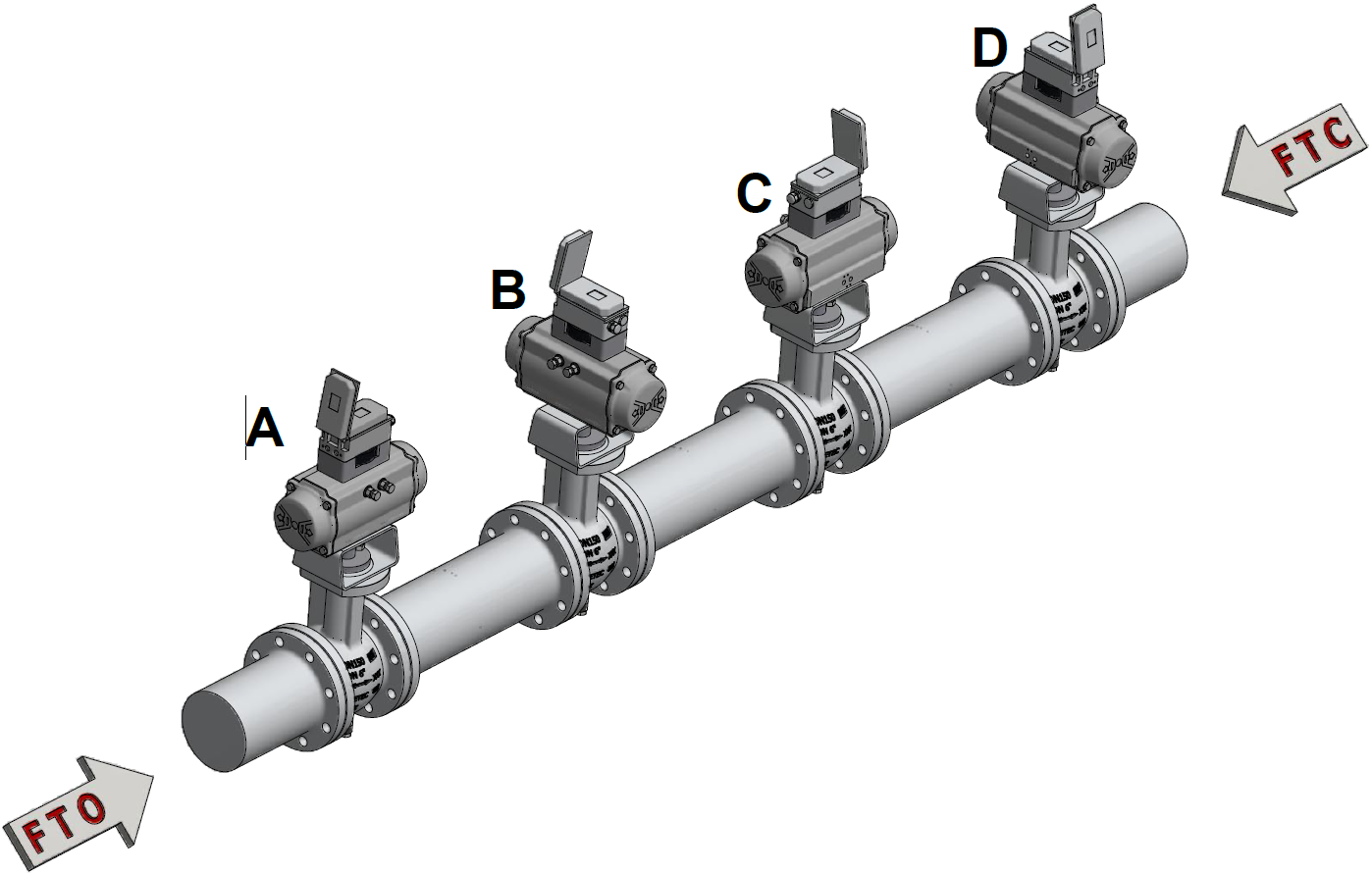
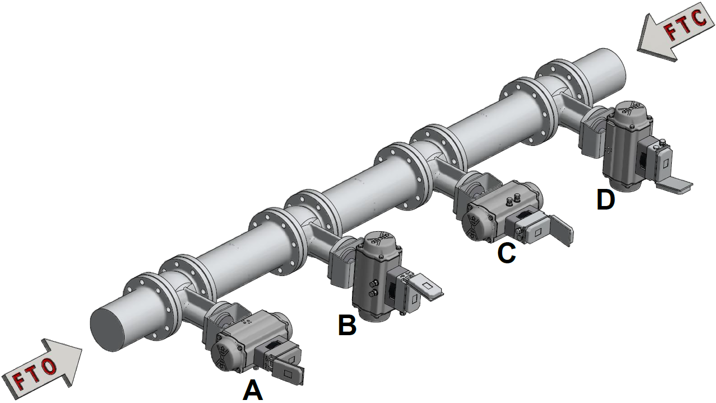
Mounting Orientations
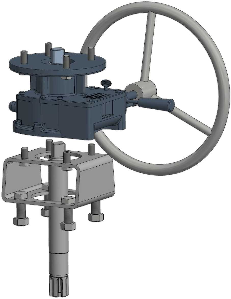
Mounting types A, B*, C and D* are possible for mounting the Type BR31a Actuator on the valve.
* For control valves with manual gearbox, mounting positions B and D must be checked due to the risk of collision with the pipeline.
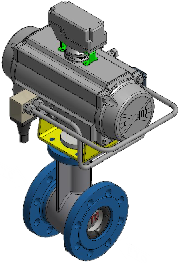
Mounting type A is selected as the standard mounting position if no other information is available.
Exemplary illustration of mounting position A. For other mounting positions, see data sheet TY005.006 (Air-Torque Actuator).
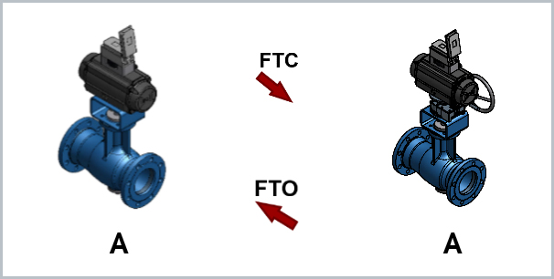
FTO = Medium opens (flow from the front, on the seat side) • FTC = Medium closes (flow from the rear)
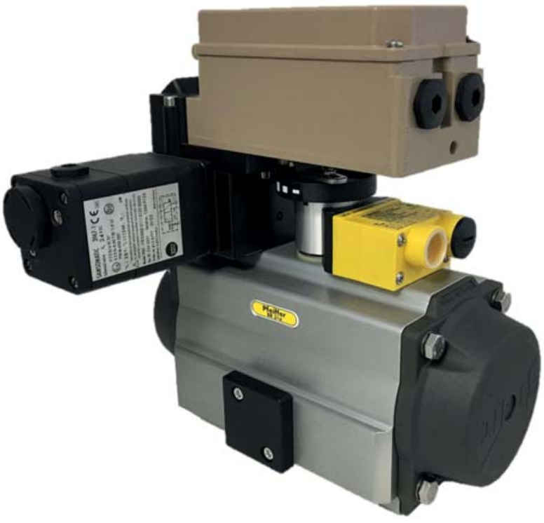
Accessories
The control valves can be equipped with various accessories: Positioner, solenoid valve, supply pressure regulator, limit switch, volume booster/booster and other attachments.
Mounting of accessories (attachments) to pneumatic rotary actuators is performed according to two standardized mounting methods:
EU/CE conformity
| Conformity declaration HE31a-01 (Pfeiffer) | RL 2014/34/EU (ATEX) | Excluded from the scope according to ignition hazard assessment according to DIN EN 13463-1:2001, para. 5.2 |
| Conformity declaration HE31a-01 (Pfeiffer) | RL 2014/68/EU (DGRL) | AExcluded from the scope of Art. 1, § 2, letter j) |
| Conformity declaration HE31a-01 (Pfeiffer) | RL 2006/42/EG (MRL) | Incomplete machine (valve actuator with or without interface according to EN ISO 5211) |